
A complete manure composting system is more than a fermentation vessel. It connects collection, feedstock conditioning, enclosed transfer, aerobic treatment, exhaust and odor handling, discharge, curing or fertilizer finishing, and controls. The interfaces between these blocks determine whether material can move through the site reliably.
At Cason, we begin system discussions with farm and site data rather than selecting one item from the equipment product range. The project team needs the manure source, daily and peak volume, collection pattern, moisture variation, bedding or other mixed material, available utilities, site layout, and intended output route before it can arrange the process blocks.
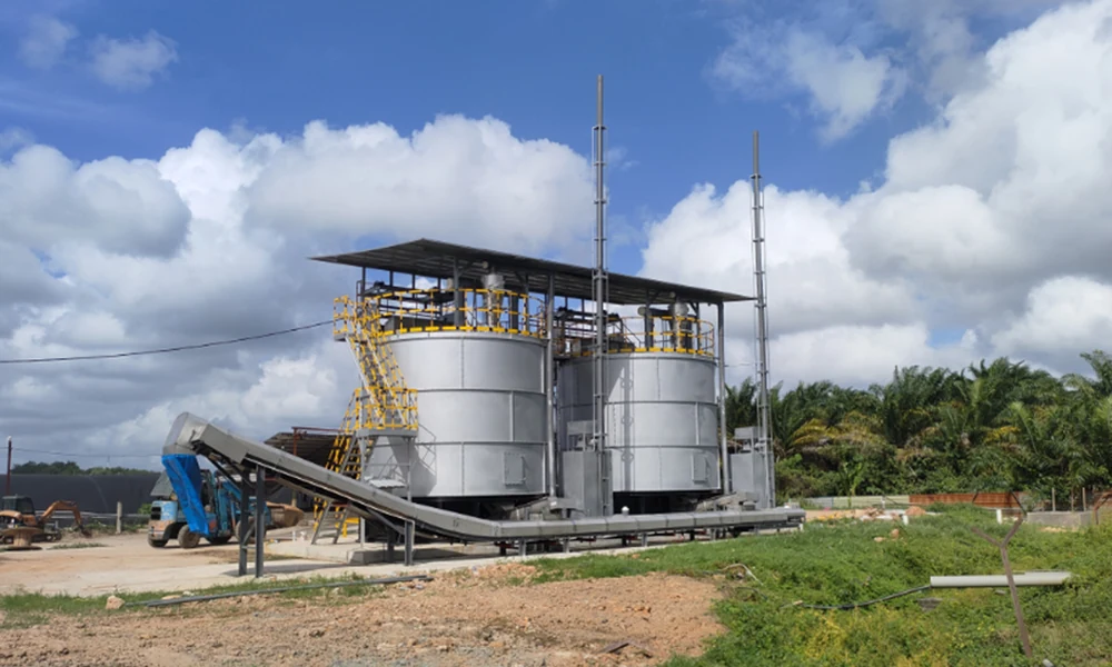
Measure manure volume and collection pattern
Start at the point where manure enters the treatment system. Record ordinary and peak daily volume, the number and timing of collection events, moisture observations, wash water, bedding, foreign material, and any temporary storage. An annual manure estimate is too broad for equipment interfaces and daily operating decisions.
Map the route from barns or collection channels to the proposed treatment area. Note elevation changes, vehicle access, drainage, separation equipment, existing pits, and distances. The map exposes whether the site can feed continuously, in batches, or only during limited operating windows.
Keep seasonal changes visible. Rain, production cycles, animal numbers, cleaning practice, and bedding can alter both volume and handling. The design basis should state which condition represents normal operation and which represents a peak that the system must manage.
Use one project data sheet:
| Input | What to record | Why it matters |
| Feedstock source | Animal type and collection route | Defines the incoming material and possible contaminants |
| Daily volume | Normal range and recurring peaks | Sets the flow basis between process blocks |
| Moisture condition | Representative measurements and variation | Guides conditioning and transfer review |
| Collection timing | Continuous, scheduled, or accumulated | Affects buffer and feeding arrangements |
| Mixed material | Bedding, bulking material, or other organic inputs | Changes handling and process assessment |
| Site utilities | Power, water, drainage, and available controls | Limits equipment and interface choices |
Define feedstock conditioning needs
Conditioning prepares the collected material for the selected aerobic route. Depending on the verified feedstock, the system review may include solid-liquid separation, dewatering, removal of unsuitable material, mixing, or addition of an appropriate conditioning material. The actual combination should come from representative material data and process testing.
Do not specify a dewatering step only because another farm uses one. First determine what arrives at the system and what the selected treatment process expects. An unnecessary step adds handling and maintenance; a missing step can shift an unsuitable feedstock into the core equipment.
The conditioning block must also define where separated liquid or rejected material goes. Moving a problem outside the main vessel does not complete the process. Drainage, storage, reuse, or further treatment routes need to appear on the site process drawing.
Add sampling and cleaning points to that drawing. Operators need a safe place to observe the incoming material, collect a representative sample, remove contamination, and wash the area without sending uncontrolled liquid into another part of the site. These details influence floor levels, drainage, access, and the boundary between civil work and equipment supply.
Connect enclosed transfer to aerobic treatment
Transfer equipment should move the conditioned feedstock without creating an uncontrolled spill or exposing operators to avoidable contact. The design team should define the feed point, elevation, distance, required containment, cleaning access, and how the transfer device starts and stops with the core treatment equipment.
Enclosed conveying can help keep the route controlled, but the exact conveyor, pump, or feeding arrangement depends on the material. The interface needs access for inspection and removal of obstructions. It should not become a sealed section that cannot be safely cleaned.
The aerobic vessel is then selected within the full system. Our guide to choosing an aerobic manure fermentation tank explains the model-selection inputs. This article does not compare individual tank models; it defines what must connect to the vessel.
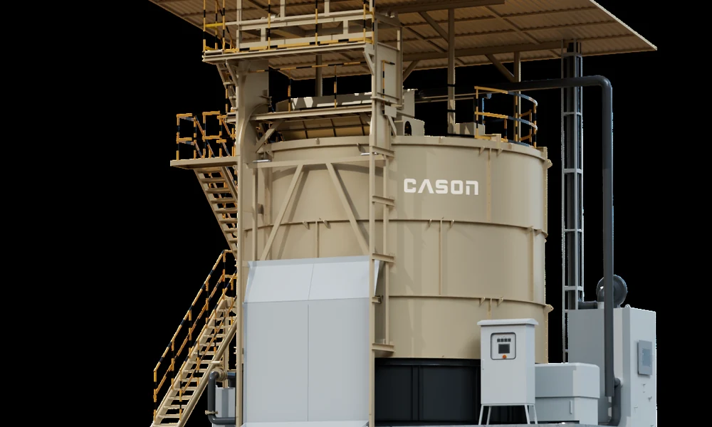
Size odor and exhaust handling interfaces
Odor handling begins by identifying every air stream and opening, not by attaching one fan to the vessel. Mark the collection or receiving area, conditioning equipment, conveyors, vessel exhaust, discharge point, curing area, and any enclosure that can release process air.
For each point, document whether it is open, locally captured, or enclosed, and where the captured air goes. The final deodorization route depends on the project, but duct paths, condensate handling, fan interfaces, maintenance access, and discharge location belong in the system layout.
Avoid promising that one device removes all odor under every site condition. Housekeeping, feedstock storage, drainage, enclosure, operating practice, and treatment equipment all influence the result. The acceptance plan should check the installed capture and routing arrangement against the approved drawing.
Plan discharge, curing and fertilizer finishing
Material leaving the aerobic vessel still needs a destination. Define how it is discharged, transferred, temporarily stored, cured where required, screened, blended, or prepared for the intended fertilizer route. The exact sequence depends on the output specification and local operating plan.
Reserve sufficient space for safe material movement and separate incoming and treated routes where practical. Consider vehicle turning, weather protection, drainage, dust management, and how operators obtain samples. A project that allocates all available space to the core vessel often discovers too late that discharge and curing cannot operate cleanly.
Cason’s system and equipment overview gives buyers first-party context for our work. A website example can support a design discussion, but it should not be copied as a complete layout. Site geometry, manure characteristics, utilities, and output handling remain project-specific.
Specify controls, alarms and acceptance tests
Controls must coordinate equipment states across the system. The team should identify which devices can run independently, which require permissive conditions, how a full or blocked section is detected, where emergency stops apply, and what information operators need to see.
Create an interface list before programming. For every process block, record its incoming signal, outgoing signal, start condition, stop condition, alarm, manual mode, and responsible supplier. This prevents gaps between packages that are individually functional but cannot operate as one line.
The list should include non-electrical interfaces as well. Identify who supplies chutes, supports, duct connections, flexible joints, drainage, platforms, guarding, and field cabling. State the design information each party must provide and its due date. A missing flange dimension or support load can delay installation even when the main equipment is ready.
Commissioning should verify both individual equipment and process handoffs. Check rotation and movement, interlocks, alarms, material transfer, containment, exhaust routing, discharge, cleaning access, and operator instructions. Performance acceptance must use the agreed feedstock and design conditions rather than an undefined demonstration load.
Plan operator training around normal starts and stops, blockage response, alarm acknowledgement, cleaning, and the conditions that require escalation. Record the accepted settings and responsibility for later changes. Controls can coordinate equipment, but they cannot compensate for an undocumented operating decision or feedstock outside the agreed basis.
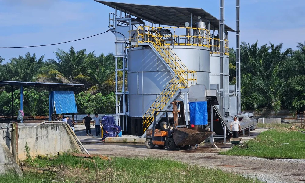
Build the process layout before confirming equipment
Arrange the project as a flow from collection to output. Mark the measured input, conditioning route, enclosed transfer, aerobic vessel, air streams, discharge, curing or fertilizer finishing, utilities, controls, and access. Then assign an owner and an acceptance point to every interface.
Review the layout with farm operations, civil, electrical, environmental, and maintenance personnel before equipment approval. Each group sees a different failure point: vehicle conflict, inadequate drainage, unavailable power, an unhandled air stream, or inaccessible service space. Closing those comments on the same drawing reduces changes during installation.
The Vietnam farm project can help buyers see equipment in an operating-farm context, while our Malaysia fermentation-system project provides another first-party reference. Neither page replaces a new project’s data sheet and engineering layout.
To start a preliminary system review, use our contact page and send the farm type, manure sources, normal and peak daily volume, moisture observations, current collection method, mixed materials, available utilities, site drawing, odor constraints, and planned output. Cason can then organize the required process blocks and identify which site inputs still need confirmation.